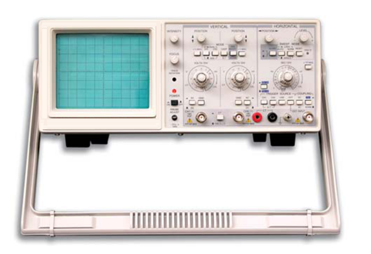
GENERAL SPECIFICATION :
This is a portable kind of oscilloscope for two traces. The bandwidth of 30MHz is 0~30MHz. its vertical deflection factor is 5mV/div and to 1mV/div by Magnification. Full bandwidth sweeping circuit is used in the sweeping system. The flexible and convenient triggering mode has the functions for selecting signals from one channel or triggered by Ext signals. And there is another function of ALT trigger to observe signals from two irrelative channels.
The instrument has the functions of TV-H, TV-V synchronization and trigger-lock to observe all kinds of signals stably. And from the terminal for trigger input, CH1 and CH2 signals can be output along with the triggering channel to connect the Ext frequency counter.
The instrument is of easy operation with comfortable controls. Its reasonable structure and technology makes it conveniently to repair and calibrate.
COMPONENT TEST :
Component tester is the special circuit with which a single component or components in or out of actual circuit board can be easily tested requiring no power to drive the circuit
TECHNICAL SPECIFICATION :
-
Y Deflection Factor-
-
Operating mode : Y1, Y2, ALT, CHOP, ADD, X-Y
-
Deflection Factor(Y1 or Y2) : 5mV/div~20V/div in 1-2-5 sequence, altogether 12 steps. Error <3%
-
MAG Rate : ×5 Error <5%
-
Frequency Bandwidth-
- AC : 10Hz~30MHz -3dB
- DC : 0~30MHz -3dB
-
Frequency Bandwidth by MAG-
- AC : 10Hz~5MHz -3dB
- DC : 0~5MHz -3dB
-
Rising time : <18ns, £ 70ns by MAG
-
Overshot : £ 5%
-
Damp : £ 5%
-
Coupling Mode : AC^DC
-
Input Impedance : 1±5%MW£30pF(direct) 10±5%MW£23pF (by probe)
-
Max Safe Voltage : 400V(DC+ACp-p)
-
Slope Inverting : Y2 only
-
Triggering System-
- Triggering Source : Y1,Y2,ALT,POWER,EXT
- Coupling : AC/DC(EXT), NORM/TV-H, TV-V
- Polarity : +, –
- Synchronized Frequency Range : Auto: 50Hz~30MHz
- Min. Synchronized Trigger Level : Trig: DC~20MHz INT: 1div; EXT: 0.2Vp-p, TV: INT: 2div EXT: 0.3Vp-pTrig Lock (50Hz~10MHz), INT: 2div
- Input Impedance (by EXT trigger) : 1±5%MW£30pF
- Max Safe Voltage : 400V(DC+ACp-p)
- Horizontal System-
- Sweep mode : AUTO,TRIG,LOCK,SINGLE
- Sweep time Factor : 0.1µs/div~0.2s/div in 1-2-5 sequence altogether 20, steps Error <3%
- MAG : ×10 Error <8%
-
X-Y Mode-
-
Signal Input : X-Axis: Y1 Y-Axis: Y2
-
Deflection Factor : Same as Y1
-
Frequency Response -
- AC : 10Hz~1MHz -3dB,
- DC : 0~1MHz -3dB
-
Input Impedance : Same as Y1
-
Max Safe Voltage : Same as Y1
-
X-Y Phase Difference : <3°(DC~50kHz)
-
Z-Axis System-
-
Min Input Level : TTL Level
-
Max Input Voltage : 50V(DC+ACp-p)
-
Input Resistance : 10kW
-
Input Polarity : Low level to brighten
-
Frequency Range : DC ~5MHz
Note - Technical Specifications & Appearance are subject to change without prior notice.
Click below to view catalogue